3-Stage Research Compressor
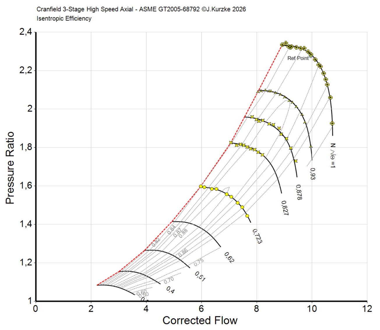
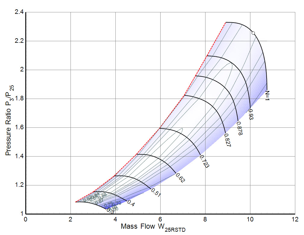
This map of a compressor with a pressure ratio of 2.4 is usefull for modeling the booster of conventional turbofans since it has a relatively low circumferential speed.
This compressor map serves as the basis for Figure 6 in GPPS-TC-2026-0083.
About this compressor
The map is based on the measured data from a research compressor with the following design data:
| Mass Flow [kg/s] | 10.6 |
| Pressure Ratio | 2.4 |
| Circumferential speed [m/s] | 268 |
| Rotational speed [rpm] | 9300 |
| Tip Diameter [m] | 0.55 |
| Radius Radio | 0.85 |
Some details:
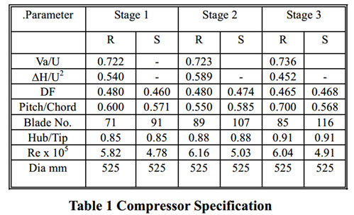
Ref.:
The Design, Development and Evaluation of 3D Aerofoils for High Speed Axial Compressors.
Part 1: Test Facility, Instrumentation and Probe Traverse Mechanism
D. Lippett, G. Woollatt, P.C. Ivey, P. Timmis, B.A. Charnley
ASME GT 2005-68792
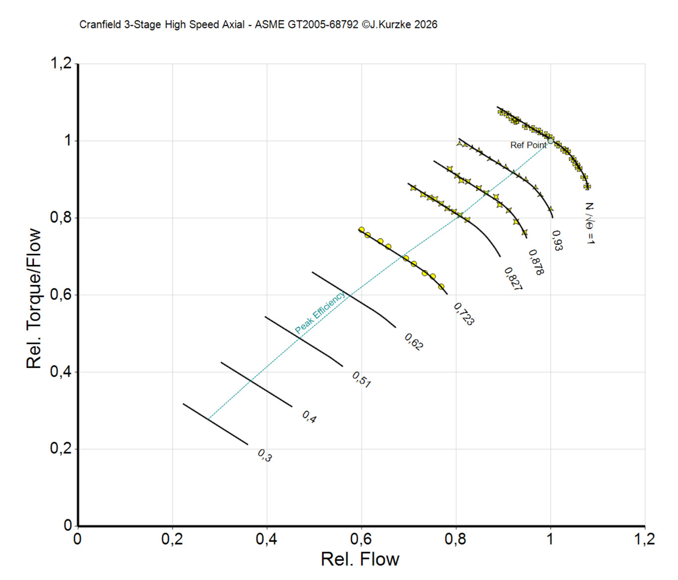
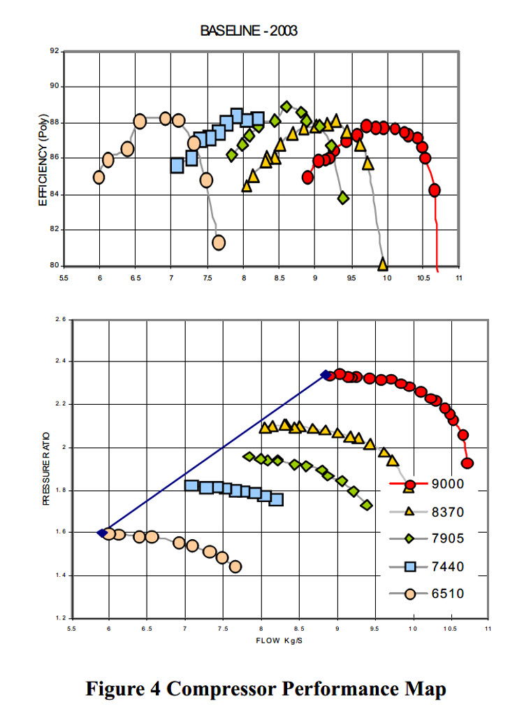
Figures of the measured data and the smooth map
Tables for use with performance programs
The map tables are available in four variants:
- ASME_GT2005-68792_PartExtndGasTurb.txt
- ASME_GT2005-68792_PartExtndNPSS.txt
- ASME_GT2005-68792_ExtndGasTurb.txt
- ASME_GT2005-68792_ExtndNPSS.txt
Note that the file extension must be changed to MAP after downloading if you want to use the map with GasTurb.
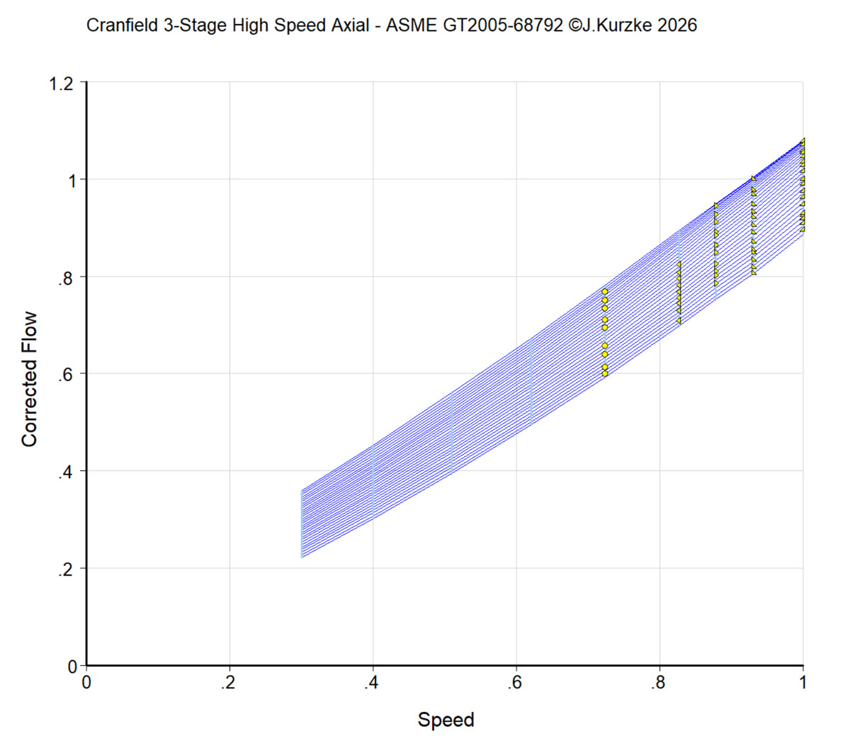
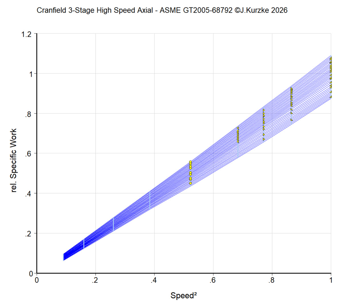
Additional figures from my experimental map smoothing program